

We cool data centers like no one else.

Next Generation Cooling for Next Generation AI

Two complementary products. One direct path from GPU heat to outside air. SCT is built for the AI data-center reality of dense racks, rising thermal loads, limited grid capacity, and water-sensitive infrastructure.

408 kWCooling capacity
≈ 1.08Estimated PUE
0 LEvaporative water consumption
~3 m2Tower footprint

Cooling capacity is a calculated rating based on measured panel performance, at 25°C ambient air. Cooling performance is also informed by laboratory testing using a controlled heat load; PUE ≈ 1.08 is a calculated estimate — full data-center PUE has not yet been measured in the field.

The AI Cooling Challenge

Most data centers cannot cool the next AI racks.

AI racks draw 130–155 kW today, and 600 kW from 2027. Most existing buildings were designed for racks below 30 kW, and the cooling infrastructure required to support new AI density is not ready.

AI GPU rack with direct-to-chip liquid cooling
130–155 kW600 kW by 2027

Heat density is rising faster than the building stock can support.

The racks already exist. The buildings to cool them do not. Many sites can host only low-density loads, while new AI deployments require direct, high-capacity thermal rejection without weeks or years of building work.

76%
of sites have no rack at 30 kW or above.
13%
of sites can host a 50 kW rack today.
$2M/MW+
and about 9 months to add a water-cooling system in many buildings.
Integrated Architecture

From GPU to outside air.

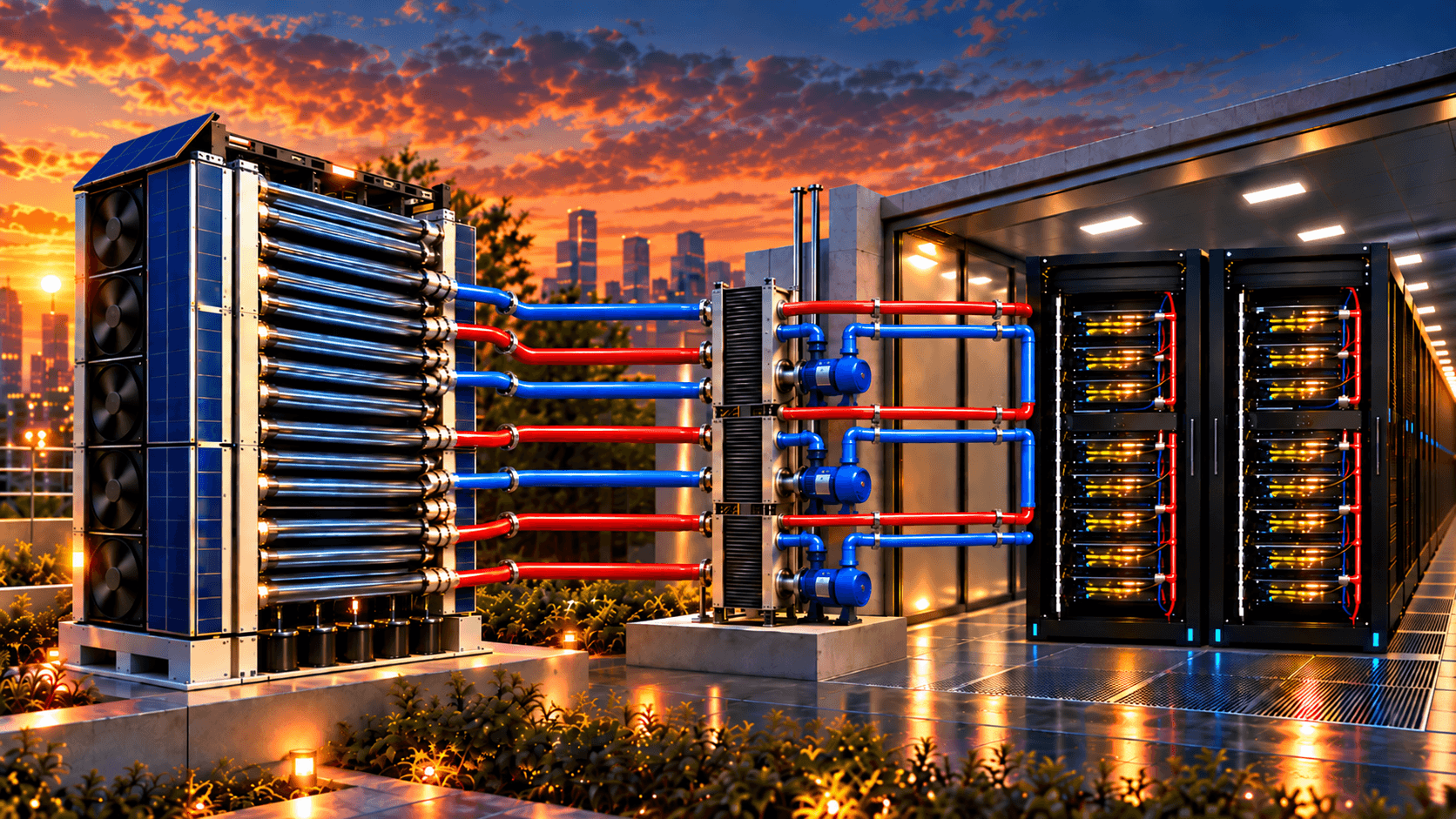
SCT combines a GPU-level cooling plate with a modular roof-mounted dry cooling tower to move heat from the chip to the outside air without a chiller and without evaporative water use.

GPU rack with direct-to-chip cold platesGPU · Cold plate
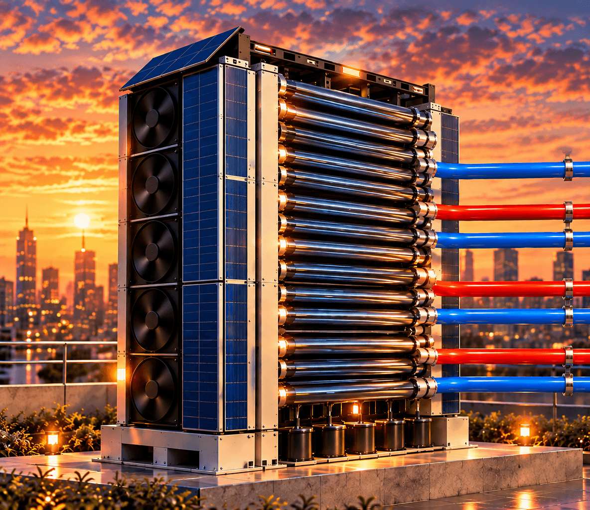
SCT modular dry cooling tower on a rooftopDry cooling tower

One Integrated Cooling System

Engineering Advantages

Engineered differently, on purpose.

SCT combines GPU-level cooling plates, independently sectioned rack piping, external pumping and heat-exchange equipment, and modular dry towers into one scalable architecture — not just a compact tower, but a deliberate set of engineering choices at every stage of the cooling path.

No Rack-Side CDU. Cooling Infrastructure Outside the IT Room.

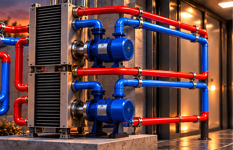
SCT’s architecture is designed without a dedicated rack-side Coolant Distribution Unit cabinet. Circulation pumps and heat-exchange equipment are located outside the IT room — sized around a current approved cooling-capacity reference of 408 kW — reducing the equipment footprint and heat contribution inside the IT space.

This equipment still performs full pumping and heat-exchange duty; it is relocated, not eliminated. A single external arrangement is not intended to serve unlimited heat load — additional capacity is added through modular expansion.

Conceptual rendering of SCT's external circulation pumps and heat-exchange equipment

UNLIMITED RACKS — Scalable Rack Cooling Architecture

Each rack is cooled through multiple independent sections and piping paths. If one section is affected, unaffected sections can continue operating — helping isolate failures rather than taking the whole rack offline.

“Unlimited” describes modular scalability, not infinite capacity. Rack scalability remains subject to total heat load, flow, piping, power, and site engineering, and this does not guarantee the affected section or the full rack remains functional in every failure scenario.

IT ROOM BOUNDARYPumps /Heat exchangeWARMCOOLSEC 01OKFAULTSEC 02OKFAULTSEC 03OKFAULTSEC 04OKFAULTSEC 05OKFAULTSEC 06OKFAULTSection affectedOthers continue operating

Independent Cooling Paths

All sections circulate coolant, each through its own dedicated path.

Localized Fault

One section develops a fault and becomes inactive.

Continued Operation

Unaffected sections keep circulating coolant without interruption.

As cooling demand grows, additional towers and supporting infrastructure can be added — subject to system engineering, not a simple drop-in addition.

Small footprint. Modular design. Easier access.

The dry cooling tower occupies approximately 3 m² of roof area, built from 8 modular sections where supported by the engineering design. Each section is intended to be serviced independently, without taking the full system offline.

Footprint reflects the tower itself, not auxiliary equipment or required service clearance.

~3 m2Tower footprint
8Modular sections
Conceptual rendering of SCT's integrated GPU cooling and dry tower system connected to a data center rack

Modular Cooling Capacity — Unlimited Racks

SCT’s cooling infrastructure is designed to scale with the data center rather than being sized once and fixed. Additional towers and supporting infrastructure can be added as cooling demand grows, subject to system engineering — and placement isn’t restricted to rooftops; siting depends on available space, airflow, structural, piping, and installation conditions.

Integrated solar panels are factored into the tower’s thermal design, intended to reduce direct solar heating without requiring a separate active cooling system for the panels themselves.

Suction-Based Cooling. Designed to Reduce Leak-Related Spray Risk.

In the negative-pressure sections of the GPU cooling path, a breach is designed to draw air inward rather than spray coolant outward. This is an engineering design objective for those sections — not a claim that the entire circuit runs below atmospheric pressure, a guarantee against every possible failure, or a claim of zero leakage risk.

Products

Two products. One integrated solution.

The SCT system is intentionally split into two products so each can be sold, installed, and operated independently while also combining into a scalable AI cooling architecture.

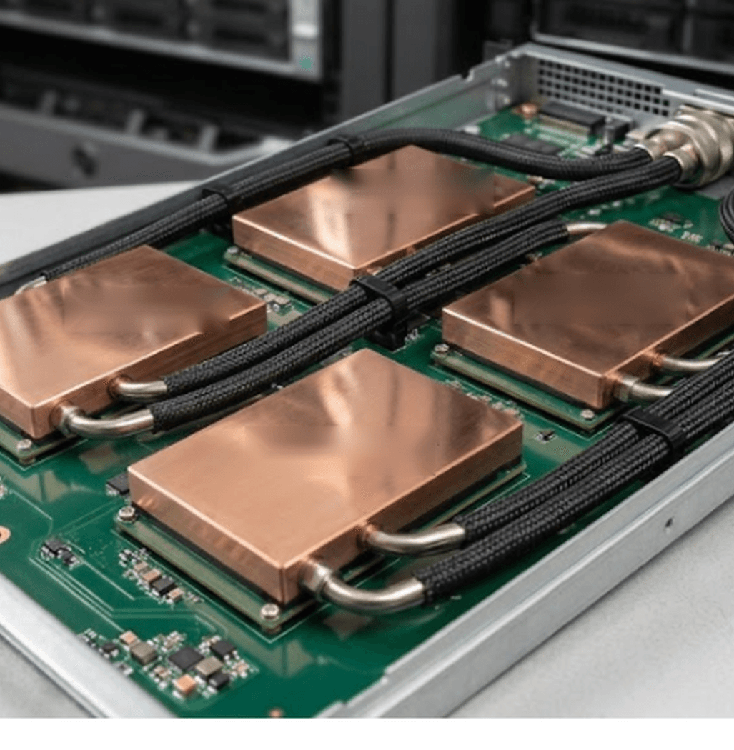
Close-up of SCT direct-to-chip GPU cooling plates

GPU Cooling Plate

Direct-to-chip liquid cooling with one plate per GPU, no internal microchannels, and suction-based coolant circulation through a multi-pipe, independently sectioned rack architecture. Designed to target approximately a 3°C temperature differential under applicable operating conditions, without requiring specialized coolant infrastructure beyond the approved working fluid and materials.

Suction-basedMulti-pipe sectionsNo microchannels
SCT modular dry cooling tower

Dry cooling tower

A modular dry tower, rated at 408 kW per unit, with 8 independent sections that reject heat from the liquid loop to outdoor air with zero ongoing evaporative water use. Designed for flexible placement — rooftop or ground-level — depending on site space, airflow, and structural conditions. Additional towers can be added as cooling demand grows, subject to system engineering.

408 kW0 L water3 m²
Performance

Source-backed engineering and efficiency signals.

SCT uses measured panel performance and benchmarked comparisons to show how the tower compares against dry coolers, chillers, and evaporative cooling strategies.

408 kWHeat removed per tower at 25°C outdoor air
3 m²Footprint on the roof
0 LEvaporative water used
ΔT ≈ 3°CTarget chip-to-coolant differential, under applicable conditions
The SCT Advantage

A different approach to cooling efficiency.

Three measurable dimensions where SCT’s dry, modular, chiller-free architecture diverges from conventional data-center cooling.

Small Footprint

A fraction of the rooftop footprint

~3 m²SCT Cooling Tower
~13–24 m²Conventional Dry Cooler

Less rooftop or yard space required per unit of cooling capacity — more flexibility for site layout.

Based on comparable heat-rejection duty. Figures represent tower/unit footprint and exclude auxiliary equipment and required service clearance. Conventional footprint varies by manufacturer and configuration.

Plan-view area, drawn to scale (side length ∝ √area)
0 LEvaporative water — normal dry operation
~50 m³Per day, per MW — evaporative tower (reference)
Zero Water Consumption

Zero evaporative water, every day of operation

No water procurement, treatment, or drought exposure for this stage of the cooling path.

SCT’s closed loop still circulates working fluid; this compares ongoing evaporative water loss only. The evaporative-tower figure is a company reference and varies with ambient conditions.

Cooling electricity

No compressors. No refrigerant cycle.

SCT’s architecture rejects heat using only fans and circulation pumps — fewer rotating mechanical components to power and maintain.

Company-provided figure, scoped to fans and circulation pumps only — not necessarily the complete electrical consumption of an installed system. Compressor-based chiller plants commonly report total electrical loads of roughly 200–380 kW/MW across compressors, pumps, and fans combined; shown here as context, not a matched-scope ratio.

SCT
~14 kW/MWFans + circulation pumps only
200–380 kW/MWConventional vapor-compression systemsReference context only — not a matched-scope electrical comparison.
Component comparison shown for context — not a proportional electrical-load chart
Leadership

Built by founders with product, field, and commercial experience.

The team is an operational mix of technical invention and commercialization for the cooling stack and AI infrastructure opportunity.

PG

Peter Garner

Co-Founder & CTO, Inventor

Inventor behind the SCT cooling platform and the technical lead for the product architecture and field validation path.

RG

Ron Golan

Co-Founder & CRO

Commercial lead focused on ecosystem partnerships, pilots, and growth across the AI infrastructure market.

Contact

Bring the cool-down challenge to SCT.

For pilots, data center conversations, technology evaluation, or commercial discussion, contact Peter directly or leave your interest and a member of the team will follow up.